
In the last post we discussed a simple method for procedurally generating 2D terrain. In today’s post, we will also generate an image that will be the final output of our program, but with a totally different purpose and method. Today we will try to generate ASCII art from images. For those of you who are not familiar with ASCII art, what we will achieve will look (more or less) like the image below.
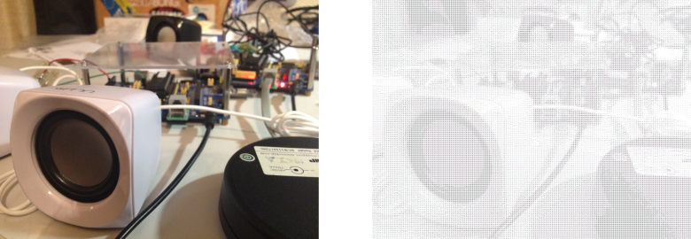
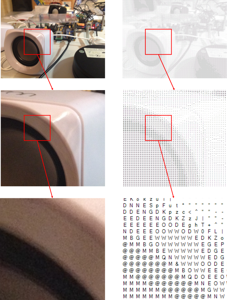
Not as impressive as you thought? If still not yet convinced (I promise this point will be revisited later on) take a look at the image at full resolution and stare at it after moving a few feet away from the screen. And yes, it is only made of ASCII characters! This can be quickly checked by zooming in any section of the image.
It should be clear from the previous example that the output image has two main characteristics: it is composed solely of ASCII characters and it looks like the original image. This is our main goal. However, we will implement and discuss some extra features or alternative implementations along the way in order to improve the results. Finally, before we embark I would like to point out three things:
- The ideas that will be explained can be extended to any kind of process were the resulting image is a composition of other images and were the aim is to resemble a target or input image.
- The post is about the algorithms and ideas that make the program work and not about a detailed explanation of the whole program.
- The example code presented is written in C#. However, the main ideas can be easily implemented in other programming languages. (Disclaimer: I am currently learning C# and this was my first project – done with learning purposes -. Sorry if the code isn’t as clean or efficient as it could be or if the project architecture isn’t the ideal one. Any suggestions on how to improve it are welcome. I am not teaching how to code in C#.)
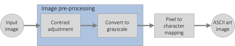
Methodology
One of the (first) things I tend to do when developing software is to devise which are the steps the program should take in order to achieve the desired outcome. It is not the only method to develop a general scheme of what the program has to do, but in this case we will work our way backwards. Starting from the ASCII art image we will try to guess from where did it come and how it was obtained.
Clearly there has been a point in the process of generating the ASCII art image where each pixel or region of pixels from the original image has been mapped to a certain character. Since the final output is the ASCII image we won’t be too wrong if we assume that this is the last step of our process.
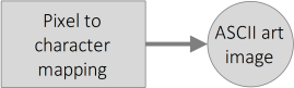
Now we have to deduce if the image used as input for the mapping is the original image or if there has been some pre-processing applied to it before this mapping step. Since the ASCII art image is made only of black characters over a white background, which from a certain distance looks like a grayscale image, a good guess is that a grayscale version of the original image is the image used as a reference for the mapping.
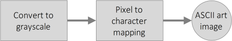
Since a grayscale version of the original image can be easily obtained from the original image the final scheme of the process is:

A more general way of defining the “Convert to grayscale” step would be “Image pre-processing”. This would include, in the case we wanted to perform more operations than just a grayscale conversion, all the different operations and transformations applied to the image before the final mapping of the image to ASCII characters.
Image pre-processing
Grayscale conversion
There are many methods that can be applied to obtain a grayscale version of an RGB image and I will only focus on the one I decided to use. What I applied is a conversion that preserves the luminance (or luminous intensity) of the original image in the grayscale image. Each pixel’s intensity or grey value is simply the weighted sum of the values of its RGB components computed as follows:
I = 0.299·R+0.587·G+0.114·B ≈ 0.3·R+0.59·G+0.11·B
It is not the most efficient way, but in C# this can be easily achieved with:
public static Bitmap Grayscale(Image image)
{
Bitmap btm = new Bitmap(image);
      for (int i = 0; i < btm.Width; i++)
      {
      	for (int j = 0; j < btm.Height; j++)
            {
            	int ser = (int)(btm.GetPixel(i, j).R*0.3 + btm.GetPixel(i, j).G*0.59 + btm.GetPixel(i, j).B*0.11);

                    btm.SetPixel(i, j, Color.FromArgb(ser, ser, ser));
            }
       }
       return btm;
}
Were we are simply traversing all the pixels in the original image, computing the weighted sum and then assigning the result as the pixel’s new intensity. Now, we could keep going from here, but since the final results depend largely on the grayscale version of the original image, wouldn’t it be nice if we allowed the user to have some control over the grayscale conversion? One way to do this is to let the user adjust the contrast of the original image and when done, convert it to grayscale. We could let the user adjust directly the contrast of the grayscale image but I preferred to develop a simple interface that only displays two images: the original and the one made of ASCII characters which is why I decided to implement the contrast adjustment on the original image.
Contrast adjustment
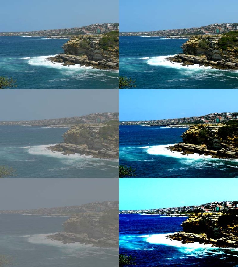
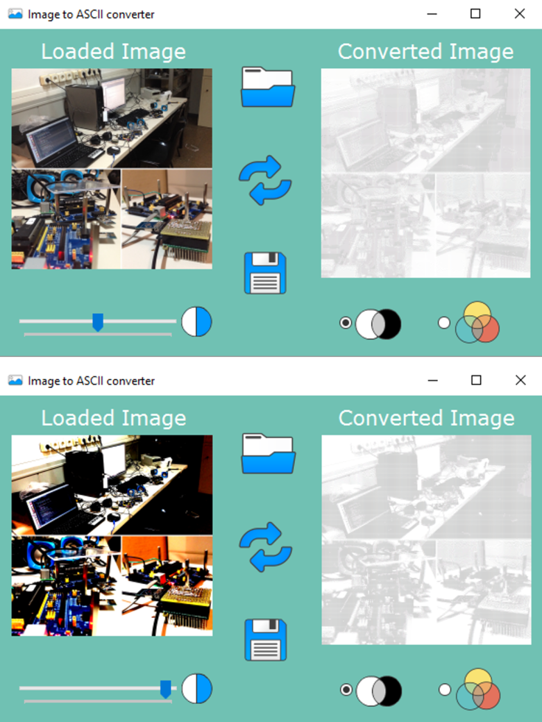
So, what is the contrast of an image and how can we modify it? Basically, the contrast of an image is the difference between the maximum and minimum pixel intensity, the “amount” of separation between its darkest and brightest areas. It is then determined by the colour and brightness of the different objects or shapes that appear in the image. This means that the higher the contrast, the bigger the difference between pixel intensities, and the easier it will be to recognize the different objects in the image (due to this bigger range of intensities). This can be appreciated in the image below.
Once knowing this it’s time to tackle the big question: How can we modify (increase or decrease) the contrast of an image?
We will achieve this by applying to the image a pixel by pixel operation (as we did when grayscaling) that modifies each pixel’s intensity with the objective of expanding or contracting the range of intensity values or luminance an image has. The value of the output image at a particular pixel will depend only on the value of the pixel located at that same position on the original image. This kind of operations are called in Computer Vision point operations.
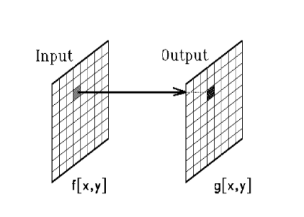
Note that this implies that two pixels that have the same intensity in the original image will be mapped to the same, and usually different from the original, intensity value in the output image. The transformation is then a single variable function
g(x,y) = T( f(x,y) )
Where g(x,y) is the intensity of the pixel (x,y) in the output image, f(x,y) is the intensity of the original image at the same position and T is the applied transformation. The pixel position in the image doesn’t play any role at all and its intensity is the only interesting property when varying the contrast. Point operations can be plotted in the same way single variable functions are. On the x axis, we will have the range of values the input property can take (I) and, on the y axis, the mapped values that result from the transformation (I’). We will make use of this to derive intuitively our contrast adjustment transformation. As an example, how would a transformation that didn’t modify the image at all look like?
Yep, that’s right. Each intensity value in the original image would be mapped to its same value in the output image. Recall now that what we want to achieve when increasing the contrast is to make wider the range of intensities in the image. Any ideas on the shape of the transformation that would achieve this? You probably guessed right. If we increase the slope of the line presented above, say double it, any considered range of intensities in the input image will be mapped to a range in the output image twice as big. And if we decrease the slope, say to a half, any considered range of intensities in the input image will half its size in the output image. This can be appreciated in the image below.
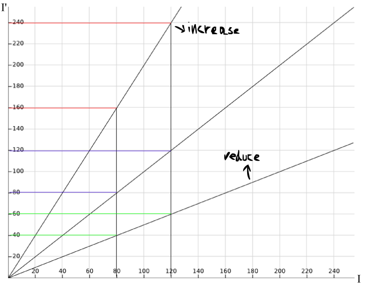
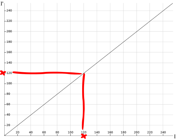
We are getting close… Note that all the lines presented above have a point in common, the origin in this case. This is nice because if we apply the transformation directly to the original image, without creating a copy of it, having a fixed point will allow us to recover the original image. This wouldn’t be possible without having a fixed point. However, is the origin the best fixed point we can get? I don’t think so. Note that increasing the contrast in this way will result in many intensities being mapped to 255, the maximum allowed intensity in images that store each channel’s intensity with 8 bits. I hope that you agree in that it would be better to divide this region of “out of bounds” intensities between the max and min allowed intensities. This would make the loss of information symmetric. This results in choosing 127.5 as the fixed point of the transformation. Then our contrast transformation so far looks like
I’ = (I-127.5)·c + 127.5
where 127.5 can be rounded to 127 or 128.
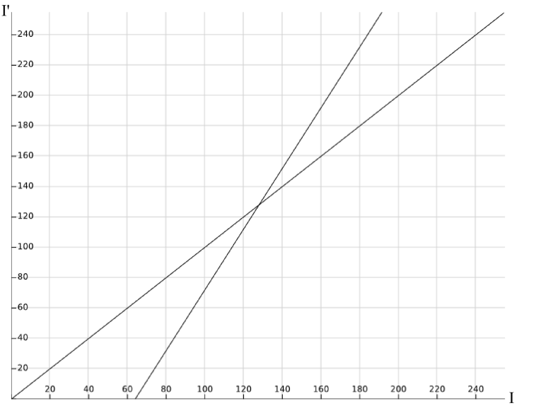
Not that difficult eh? See how in the previous figure half of the values “out of bounds” get mapped to 0 and the other half to 255? The value of c will be the one that decides how much we increase or decrease the contrast. Its value can be decided in many ways. In my case I am using a quadratic function to determine the value of c. A scrollbar in the GUI of the program reads a value between -100 and 100. This value is then mapped to the range [0,2] and squared, so that c finally varies between 0 and 4. Finally, note that once knowing the value of c the mapping of intensities can be already computed so storing the transformations in a lookup table will improve the efficiency and speed of this step.
The code below, which is in charge of varying the contrast should now be easy to follow. It is based on this BitBank’s stackoverflow answer.
public unsafe static void AdjustContrast(Bitmap bmp, double contrast)
{
{
      	byte[] contrast_lookup_table = new byte[256];
            double newValue = 0;
            double c = (100.0 + contrast) / 100.0;

            c *= c;

            for (int i = 0; i < 256; i++)
            {
            	newValue = (double)i;
                  newValue /= 255.0;
                  newValue -= 0.5;
                  newValue *= c;
                  newValue += 0.5;
                  newValue *= 255;

                  if (newValue < 0)
                  	newValue = 0;
                  if (newValue > 255)
                  	newValue = 255;
                  contrast_lookup_table[i] = (byte)newValue;
            }

            var bitmapdata = bmp.LockBits(new Rectangle(0, 0, bmp.Width, bmp.Height),
            System.Drawing.Imaging.ImageLockMode.ReadWrite, System.Drawing.Imaging.PixelFormat.Format32bppArgb);

            int PixelSize = 4;

            for (int y = 0; y < bitmapdata.Height; y++)
            {
            	byte* destPixels = (byte*)bitmapdata.Scan0 + (y * bitmapdata.Stride);
                  for (int x = 0; x < bitmapdata.Width; x++)
                  {
                  	destPixels[x * PixelSize] = contrast_lookup_table[destPixels[x * PixelSize]]; // B
                  	destPixels[x * PixelSize + 1] = contrast_lookup_table[destPixels[x * PixelSize + 1]]; // G
                  	destPixels[x * PixelSize + 2] = contrast_lookup_table[destPixels[x * PixelSize + 2]]; // R

                  }
            }
            bmp.UnlockBits(bitmapdata);
}
}
I think that’s enough for today. We now have finished the pre-processing of the image (contrast adjustment + grayscaling) and on the next post we’ll see how to finally get the ASCII image. If you enjoyed it so far be sure to stay tuned for part 2!
PS: If you want to play with the code or take a look at it, it is available here. I wanted to upload the final program (.exe) somewhere so you can download it and play with it. However, I have no idea on the best way to achieve this so it is easy for you to get it. If you have any ideas please tell me. In the meantime, you can reach me and ask for it via e-mail at juangallostra@gmail.com
Update: You can download the compiled program now here. (Thanks to Campbell for pointing out that this could be easily done via Github releases.)
PS2: I know I haven’t revisited yet the point I made at the beginning but I will, for sure, revisit it on the next post.

If you want to distribute a compiled executable, just use the GitHub releases feature,
LikeLiked by 1 person
Thanks for pointing that out. Done!
LikeLike
I did some work like this myself, a couple of years ago. I don’t believe I went into as much detail “on the front end” as you did – – contrast adjustment, “proper” RGB-to-grayscale algorithm, etc. I *think* I just grabbed the Green channel (that in which the human eye is most sensitive to brightness; poor man’s gray channel), and simply started from “contrasty” original images. I’m definitely going to read more carefully your discussion of contrast adjustment.
One thing I did differently than you did, was inspired by the old-school ASCII art that was rendered on line printers on IBM mainframes using FORTRAN. Namely, on the output end, they used multiple passes of characters, *overstruck*. Like, a ‘+’ and an ‘o’ at the same place on the paper would give you a “gunsight” -like “crossed circle.” The fun part was to work out what three letters should be overstruck to produce a given grayscale level. I’ll keep my technique to myself for the moment, against the possibility of doing my own writeup like yours sometime.
*Printing* three layers of overstruck ASCII was a challenge, as well. Suffice it to say that I was able to achieve it. However, as a consequence I found I had to directly control the (X, Y) placement of each individual character, and I haven’t quite got *that* right, yet, either – – too much white space between characters, which has the net effect of “washing out” the printed image.
Another interesting challenge is that the overall distribution of achievable grayscale densities is not uniform from “no ink” to “fully filled in” (the latter unachievable in three passes, at least in the font I used). So, strictly speaking, one ought to dither the image against the available palette – – but I haven’t done that, yet, either.
Lastly, I did all this in Perl, for quickness of iteration in development, so it runs kind of slowly. Once I get everything perfected I may rewrite it into a compiled language.
Feel free to email if you want to chat privately about any of this.
LikeLiked by 1 person